New here? Check out the “Beginner's Guide to SK8CAD”:
Browser/Enviroment: we recommend using Mozilla Firefox or Google Chrome web browsers for best performance. If you experience issues, please try using another browser or your browser's private browsing mode.
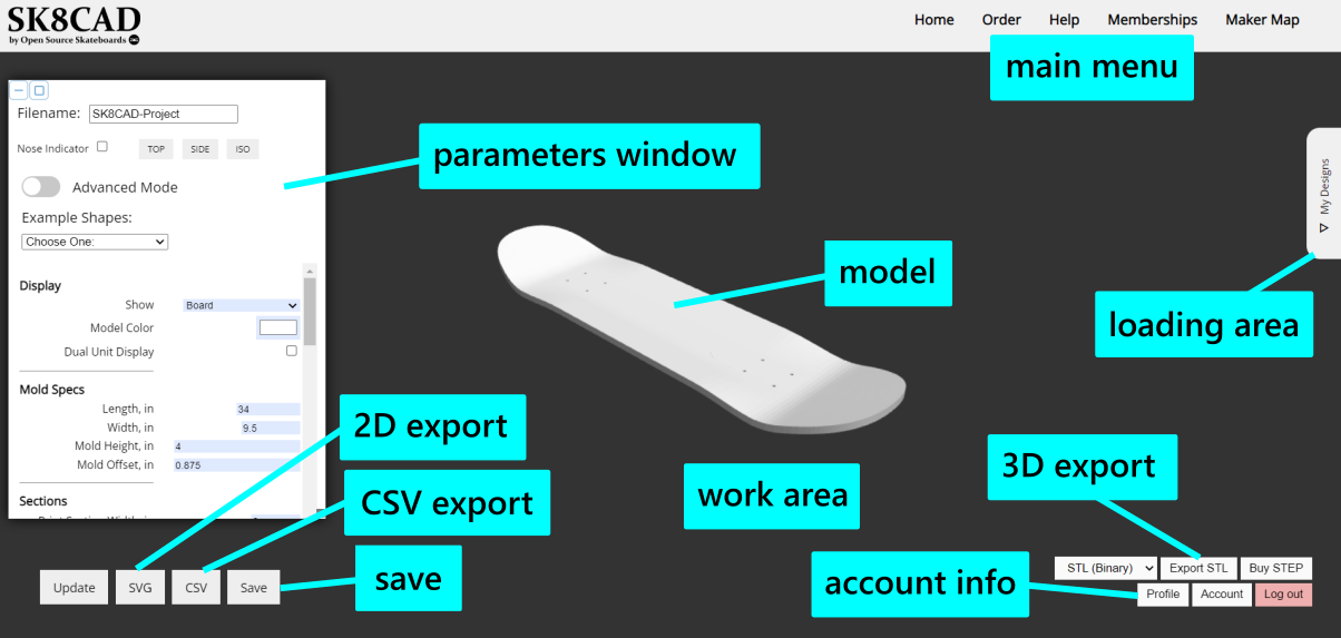
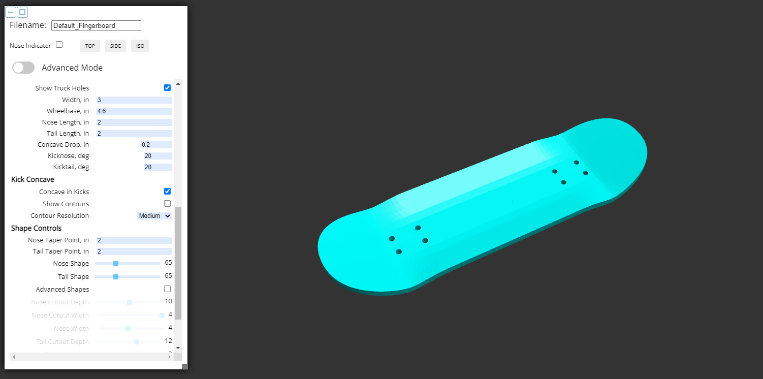
Model: the object being designed.
Parameters window: use the parameters here to design your model and choose what is shown in the work area. This window can be minimized and maximized using the buttons in the top left corner. It can also be resized using the grey square at the bottom right.
2D export: exports a 2D SVG file of your board's profile. For CNC machining, use this SVG and then project the SVG to your 3D model of a male or female mold in your CAM software. This is a top view profile, not a flattened profile - this means that the curves of the board are not accounted for, so if you cut a template from this file and lay this directly on your board, the shape will distort (unless your board is totally flat).
3D export: exports a 3D STL file of the model. The STL meshes can be a little messy - if you have a bug in the model, you can sometimes eliminate it by making very minor tweaks to the model. It can be very challenging to modify the mesh once exported.
CSV export: exports a snapshot of your current specs into a CSV file. CSV files cannot be loaded directly into SK8CAD.
Save: saves your design to your local computer. Saved files can be reloaded in the loading area. Upgrade your subscription for access.
Account info: update your public profile info (displayed on the Maker Map) and the status of your SK8CAD account.
Loading area: open the "My Designs" tab to load designs from your local computer or load Shape Library shapes. Upgrade your subscription for access.
Rotate the model: left mouse click + drag OR drag finger.
Zoom in/out: zoom wheel, pinch touch pad, OR pinch fingers.
Move the model (pan): Shift + left mouse click + drag OR hold finger, then drag finger.
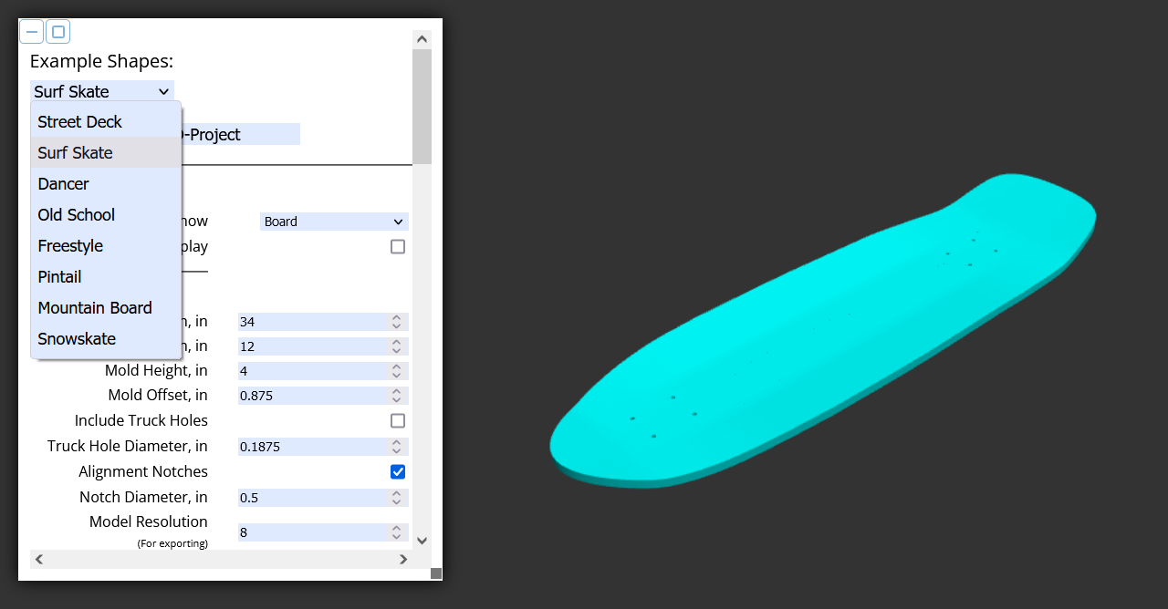
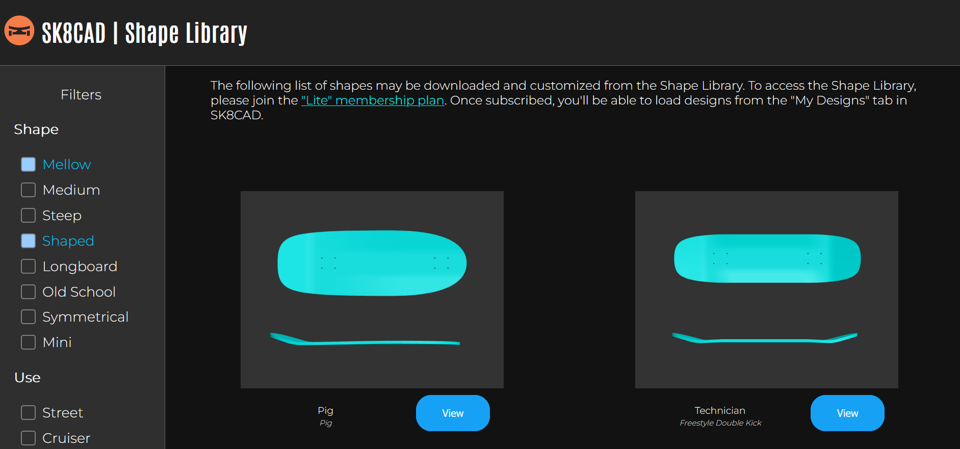
Choose a design from a variety of example board shapes, or simply use one of these options as a starting point.
The name of the file that is exported.
Show: choose which model to show.
Board: the deck, designed to your specs.
Male Mold: male mold half, designed to your specs.
Female Mold: female mold half, designed to your specs with offset accounted for.
Inverted Male Mold: a mold for casting the male mold, as defined above.
Inverted Female Mold: a mold for casting the female mold, as defined above.
Both: both the male and female mold, spaced at the offset specified.
Shaper: a shaper template model (a male mold with the profile of your design).
Dual Unit Display: show parameter values in cm.
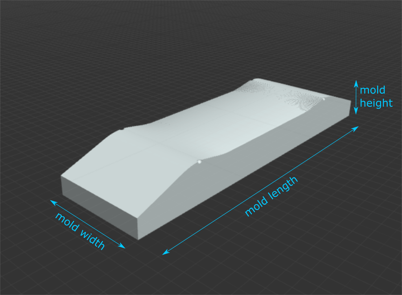
Length: length of your mold, in inches (make sure this is at least as long as your deck).
Width: width of your mold, in inches (make sure this is at least as wide as your deck).
Mold Height: the thickness of your mold, from the base to the highest point, in inches.
Mold Offset: the amount to offset the curves of the mold surfaces; this is equal to [your deck thickness] x [the number of decks you will press at a time] + [total thickness of any buffer/liner/spacer material that goes in your molds when you are pressing]. (For example, if you are pressing two decks at a time that are each 7/16” thick with 1/16” buffer material on either side, your total offset will be [7/16”] x [2] + [1/16” x 2] = 1”.
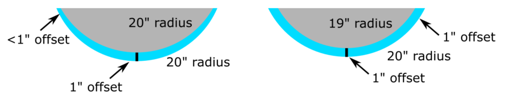
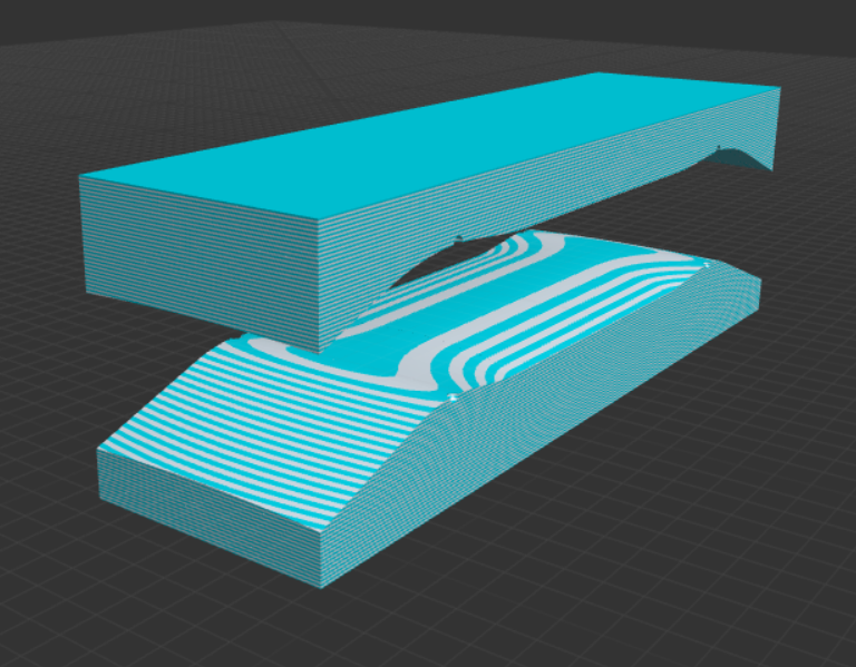
Left: mold surfaces that are not offset result in uneven pressing, which can lead to too much pressure in some spots and not enough in other spots and mellower skateboard curves.
Right: properly offset mold surfaces provide even pressure to create the strongest board that matches your design.
Include Truck Holes: creates a model with holes through the entire model per your specified bolt pattern.
Truck Hole Diameter: set the diameter of the truck holes.
Truck Hole Length: set the center to center distance of the truck holes along the length of the board.
Truck Hole Width: set the center to center distance of the truck holes along the width of the board.
Alignment Notches: places round notches at the base of the kicks, at a depth of the radius of the notch.
Notch Diameter: set the diameters of the alignment notches.
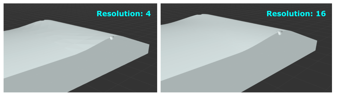
Model Resolution: adjusts the step size of the transition section of the model. A larger value will create a finer, more detailed resolution, but rendering times will be longer. If your models have any bugs, adjust this parameter to try and eliminate them (using a number divisible by 4 typically works best).
Print Section Width: set the width of the mold section. NOTE: this doesn't actually change the width of the sections, but setting this parameter will let you know if your mold is too wide for dividing into sections.
Print Section Length: set the length of the mold section. NOTE: the end sections may be shorter than this specified length.
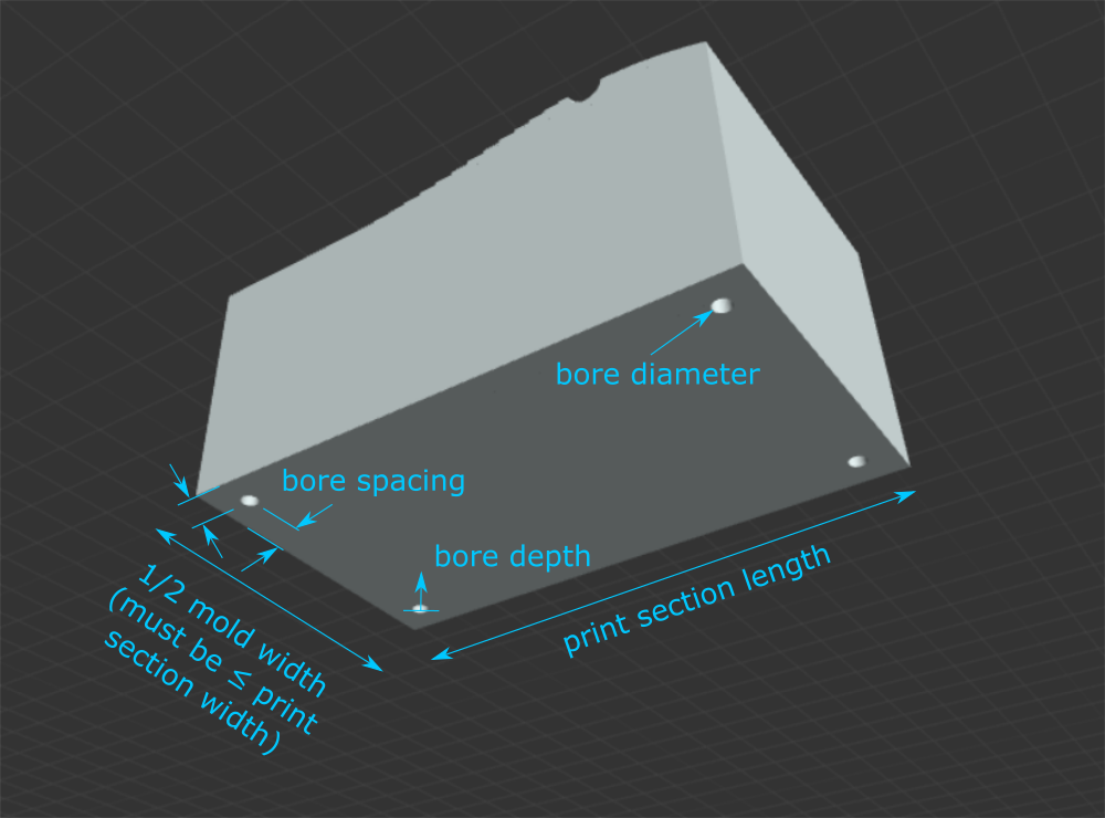
Mold Bores: make bore holes on the back side of the male and female mold surfaces (helpful for installing threaded inserts or screwing into). (Note, this will cause rendering to take longer, so it is recommended you design your board without this on first to ensure the model renders properly, then turn the bores on.)
Bore Diameter: set the diameter of the bore.
Bore Depth: set the depth of the bore (measured from the back of the mold surface).
Bore Spacing: the distance from the edge of the print section to the center of the bore.
Section to Download: This breaks the model into sections no larger than 8” x 8” to accommodate 3D printers with small bed sizes and smaller CNC machines. Unless your mold width is less than or equal to your print section width, each section only includes half of the mold width, so you will need to make two of each section for the left and right sides of your molds.
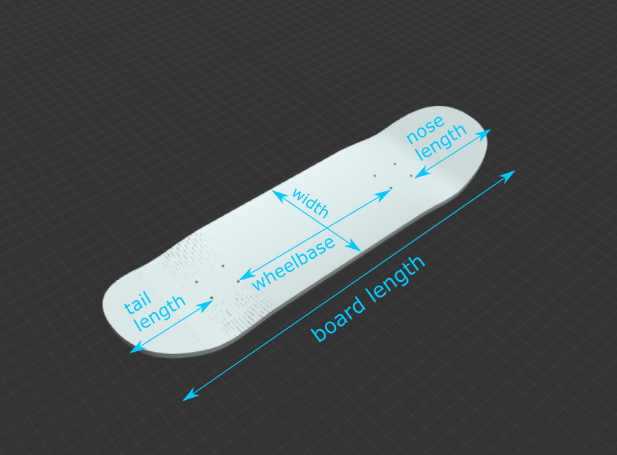
Board Length: The length of your board, from the tip of the nose to the tip of the tail, measured straight across without accounting for curvature, in inches.
Board length = [wheelbase] + [nose length] + [tail length] + [2 x truck hole length].
To change your board length, adjust one of the other four parameters.
Show Board Outline, Only: when checked, displays a 2D model of the skateboard shape, which speeds up rendering time to help make designing shapes easier.
Show Uncut Deck: when checked, displays a 3D model of the uncut board shape, with a length and width equal to your mold length and width.
Board Thickness: sets the thickness of your board model.
Show Truck Holes: when checked, shows the board model with truck holes.
Width: The width of your board at its widest point, in inches.
Wheelbase: The distance between the centers of the innermost truck holes, in inches.
Nose Length: The distance from the tip of the nose to the center of the outermost truck holes closest to the nose, in inches. This is a projected length that does not account for curvature in the nose.
Tail Length: The distance from the tip of the tail to the center of the outermost truck holes closest to the tail, in inches. This is a projected length that does not account for curvature in the tail.
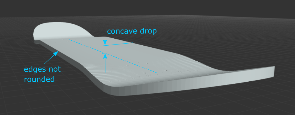
Concave Drop: The vertical distance, in inches, from the center of your board to the top of the side of your board at its widest point, before rounding over the edges.
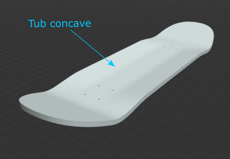
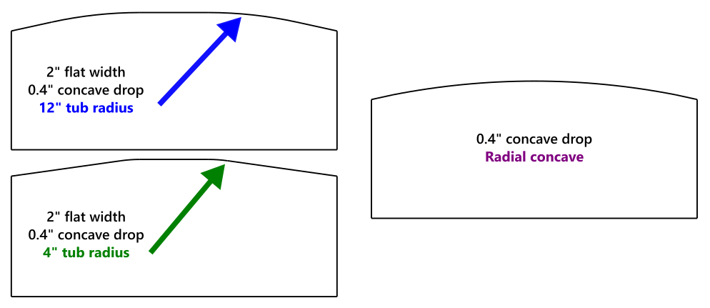
Tub Concave: Check this box to create a tub/progressive concave with a flat center section and a specific radius of curvature and angle to meet the desired concave drop. If not selected, the concave will be radial.
Flat Concave Width: (Tube concave, only.) The width of the flat section of the concave.
Tub Radius: (Tub concave, only.) The radius of curvature away from the flat section of the tub concave. A smaller radius will create a tighter, more kinked bend. A larger radius will feel more gradual. Too large of a tub radius with too large of a flat concave width to achieve your specified concave drop will result in an error.
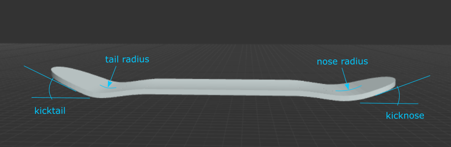
Kicknose: The angle of the nose, in degrees. There is no concave in the kicknoses at this time.
Kicktail: The angle of the tail, in degrees. There is no concave in the kicktails at this time.
Nose Radius: The radius of the curve that leads to the kicknose angle, in inches. A smaller radius will create a steeper feeling board.
Tail Radius: The radius of the curve that leads to the kicktail angle, in inches. A smaller radius will create a steeper feeling board.
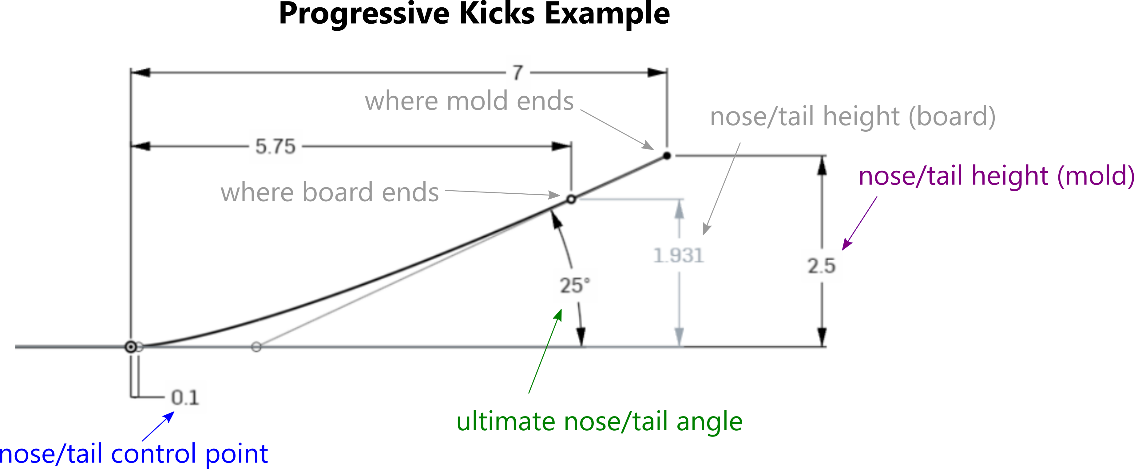
Progressive Kicks: Check this box to change angled kicks to progressive kicks. Progressive kicks are controlled by Bezier curves, and allow for continuous curvature through the kicks.
Ultimate Nose / Tail Angle: The steepest angle of the kick, at the tip of the nose or tail of the mold. Since your board should be shorter than your mold, the steepest angle of your board will be slightly less. A large ultimate angle will create a rounder kick.
Nose / Tail Height (Mold): The height of the tip of the nose/tail of the mold from the base of the deck. To help with setting this value, the height at the tip of the nose/tail of the board is also shown (this is controlled by the nose/tail height and the nose/tail length, plus the other progressive kick values).
Nose / Tail Control Point: The distance of the control point at the base of the kick from the base of the kick. The smaller this value, the "tighter" or "steeper" the kick may feel, and less curved it may be without having to increase the ultimate angle.
Progressive Kick Resolution: This controls the resolution of the curve creating the progressive kicks. Aside from allowing you to adjust modeling speed/quality, you can also tweak this value to sometimes fix a model that is not rendering properly.
Note: When "Add Rocker" is selected, extra length is added to the mold - so, these parameters that control the specs at the end of the mold are actually controlling a virtual end of the mold further out in space. In other words, these seemingly arbitrary specs feel even more arbitrary when rocker is selected. So, watch the nose/tail height of the board display (shown below the nose/tail height specs), because this will decrease when rocker is selected.
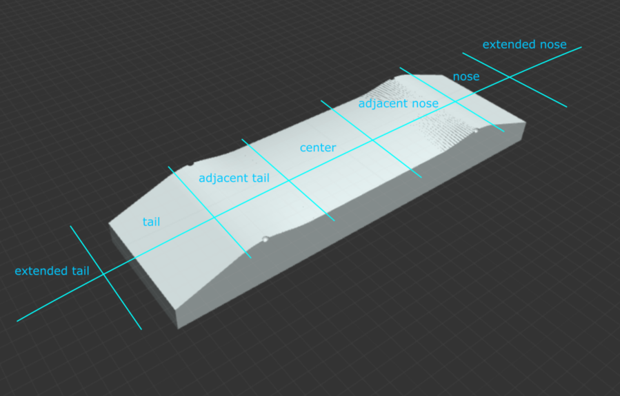
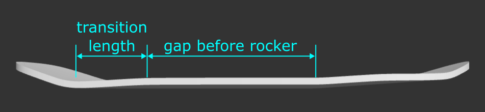
Transition Length: The length from the base of the kick to the point where full concave drop is achieved, in inches. Smaller transition lengths require more force.
Kick Gap: The distance from the centers of the outermost truck holes to the beginning of the kicks, in inches. Also referred to as “fingers of flat” by Paul Schmitt. A larger kick gap will create a mellower feeling board.
Concave in Kicks: Select this to add radial concave in the kicktail and kicknose.
Nose Base Drop: The vertical drop from the edge of the mold to the middle of the mold at the base of the kicknose. The curvature here is radial.
Additional Angle - Nose (Angled Kicks): The additional kicknose angle along the edge of the mold; the larger this value, the more concave towards the tip of the mold.
Additional Radius - Nose (Angled Kicks): The increase in nose kick radius along the edge of the mold; the larger this value, the more the concave in the kick will reduce just past the base of the kick (this can be helpful for achieving the desired geometry / reducing stress in wood during pressing).
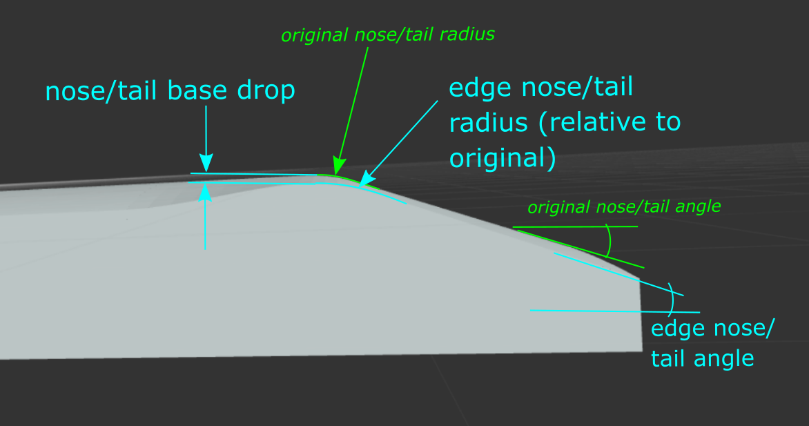
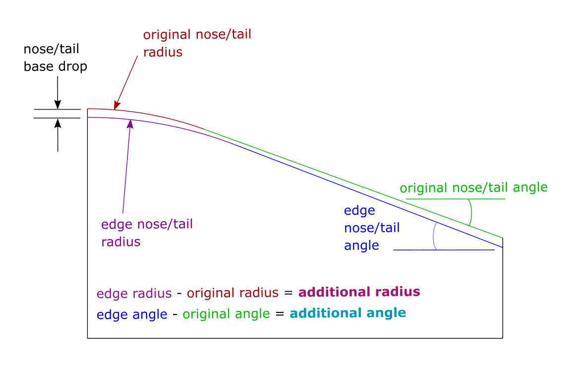
Tail Base Drop: The vertical drop from the edge of the mold to the middle of the mold at the base of the kicktail. The curvature here is radial.
Additional Angle - Tail (Angled Kicks): The additional kicktail angle along the edge of the mold; the larger this value, the more concave towards the tip of the mold.
Additional Radius - Tail (Angled Kicks): The increase in tail kick radius along the edge of the mold; the larger this value, the more the concave in the kick will reduce just past the base of the kick (this can be helpful for achieving the desired geometry / reducing stress in wood during pressing).
Additional Ultimate Angle - Nose/Tail (Progressive Kicks): The increase in ultimate nose/tail angle at the sides of the mold; the larger this value, the more the concave will mellow out in the middle of the kick.
Additional Height - Nose/Tail (Progressive Kicks): The increase in nose/tail height along the side of the mold; the larger this value, the more the concave will be in the kick towards the end of the mold.
Additional Control Point - Nose/Tail (Progressive Kicks): The increase in length of the nose/tail control point closest to the base of the kick along the sides of the mold; the larger this value, the more the concave will mellow out towards the center of the kick.
Kick Concave Resolution: Increase this value to produce a more detailed model, and reduce to produce a faster-loading model. (You can also adjust this to debug a model with rendering issues.)
Show Contours: Select this to show contour lines to better visualize the mold geometry. (Note, this will cause rendering to take longer, so it is recommended you design your board without this on first to ensure the model renders properly, then turn the contours on.)
Contour Resolution: Adjust the number of contour lines (the finer the resolution, the longer the model will take to load).
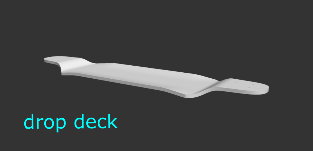
Make Drop Deck: Create a "drop" feature in the board (make the area between the trucks lower).
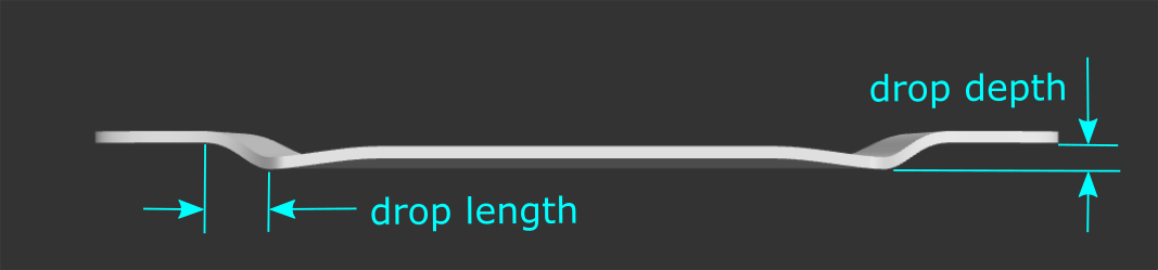
Drop Depth: The difference in height from where the trucks are mounted to the lowest dropped portion of the deck (measured in the middle of the concave).
Drop Length: The distance of the portion of the deck where the drop occurs (the drop transition area). A longer drop length will be less steep.
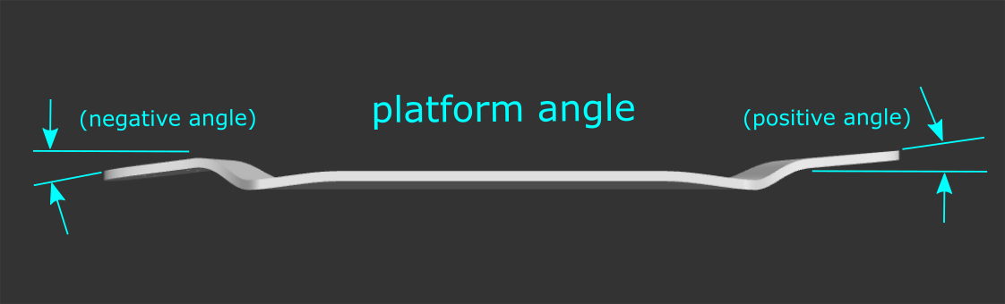
Nose/Tail Platform Angle: The angle of the section of the deck where the trucks are mounted (platform). This may be positive or negative.
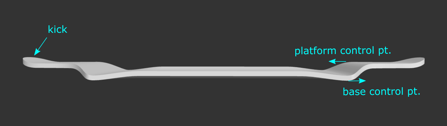
Base Control Pt: How sharp of a bend occurs at the transition from the dropped portion of the deck to the drop transition. A larger number will be more gradual. Recommended range: 0.8" - 1.5".
Platform Control Pt: How sharp of a bend occurs at the transition from the raised truck area of the deck (platform) to the drop transition. A larger number will be more gradual. Recommended range: 1.2" - 2".
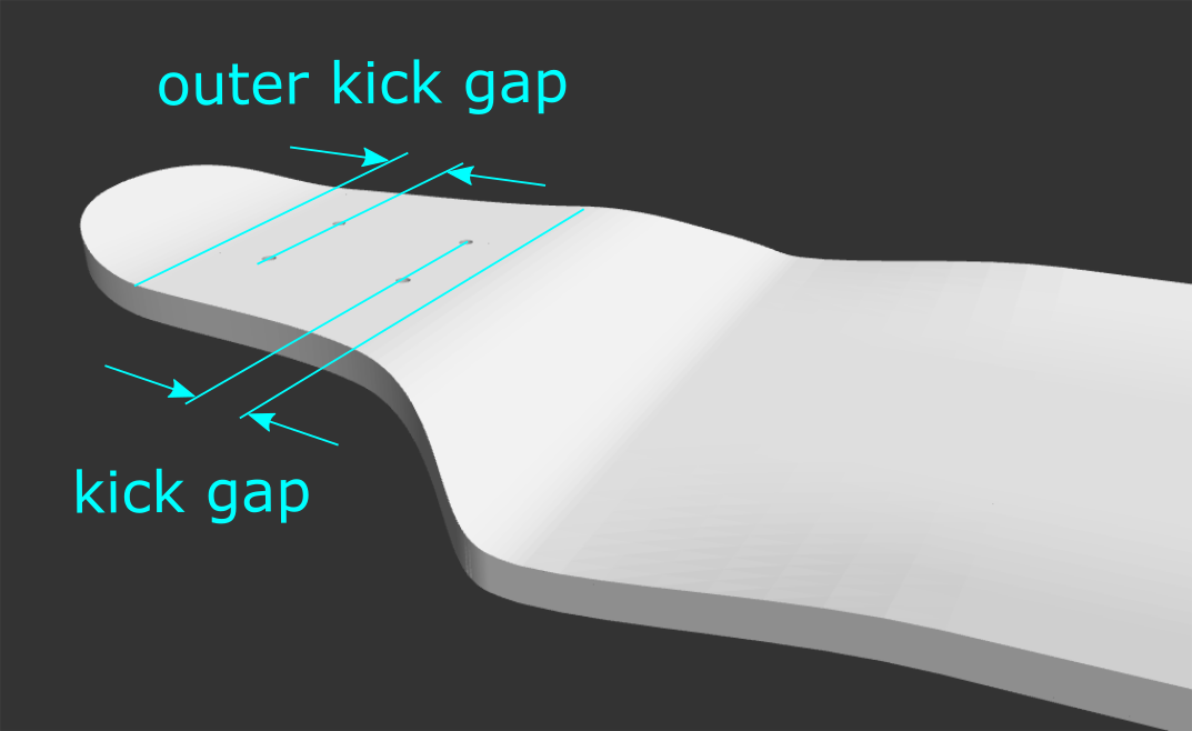
Make Kicks: Add kicks in the raised portion of the deck where the trucks are (the platform). Drop deck kicks can only be defined with the angled kick parameters of nose/tail angle and nose/tail radius (in the Board Specs section).
Outer Kick Gap: This is the kick gap of the kicknose or kicktail. Note: the normal kick gap parameter (found in the Board Specs section) controls the distance between the innermost truck holes and the beginning of the drop transition.
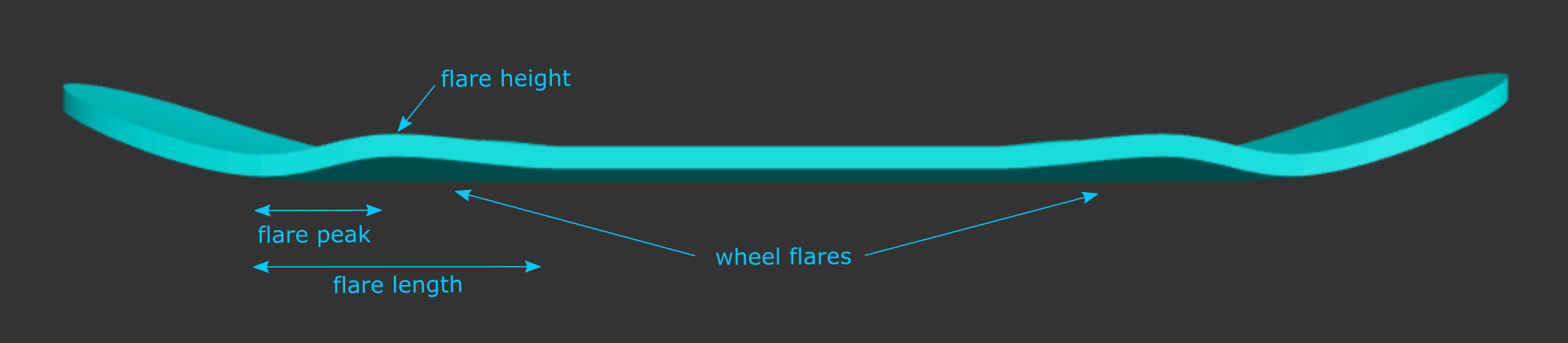
Add Wheel Flares: Add an area of deeper concave right before the kicks.
Flare Height: The concave drop of your specified deck width at the peak of the wheel flare.
Flare Peak: The distance from the beginning of the kick to the peak of the wheel flare, along the length of the board.
Flare Length: The entire length of the wheel flare feature (measured from the beginning of the kick to the point where your specified concave drop is reached).
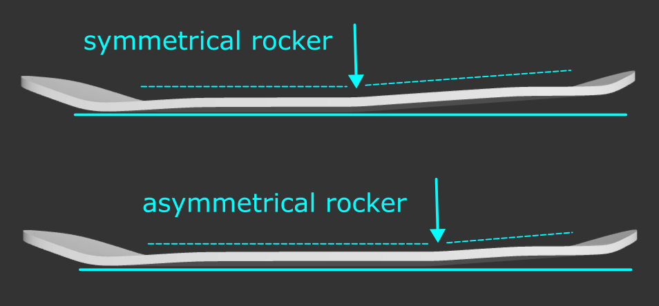
Add Rocker: Add curvature in the board from nose to tail, between the transition sections.
Note: Rocker is experimental at this time. It is currently unsupported for drop decks, boards with radial concave, single kicks, and with mold alignment notches. Truck holes on boards and molds made in SK8CAD will not be correctly generated (they cut along the z-axis, not perpendicular to the board).
Design Tip: When rocker is added, you may need to increase the height of your mold and/or reduce the nose length because the nose will extend further in the direction of the kick.

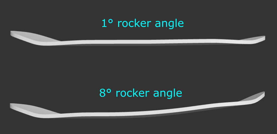
Rocker Angle: Angle of rocker relative to the ground (horizontal plane).
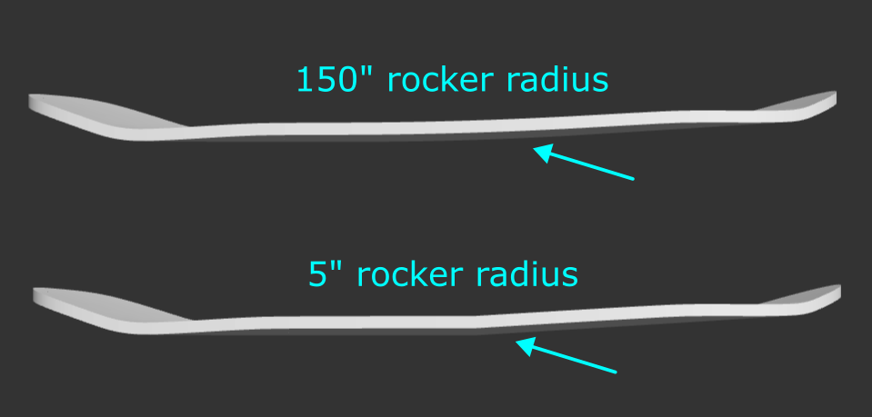
Rocker Radius: Radius defining the curvature of the rocker. A smaller radius will create a sharper bend and a larger radius will create a gradual curve.
Make Symmetrical: SK8CAD rocker is defined by a radial curve in between the kicks of the board. Checking this box makes the length on either side of that radial curve equal.
Gap Before Rocker: If rocker is not symmetrical, you can define where you'd like the rocker curvature to start - this is the distance from the end of the transition section at the tail to the beginning of the rocker curve.
"Nose Indicator": This button (in the top left of the parameters window) shows the direction of the nose of the board and displays a square at the start location of the rocker (defined by "Gap Before Rocker") since it can be difficult to see a subtle curve.
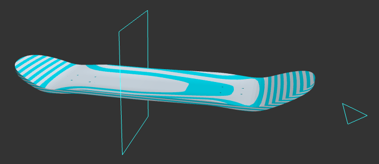
"Nose Indicator" box checked and "Show Contours" checked.
Nose Taper Point: The distance from the tip of the nose to the point where the rails (edges) of the board become parallel. For egg shapes, increase the taper point.
Tail Taper Point: The distance from the tip of the tail to the point where the rails (edges) of the board become parallel. For egg shapes, increase the taper point.
Nose Shape: The squareness of the nose. The closer to 100, the squarer the nose.
Tail Shape: The squareness of the tail. The closer to 100, the squarer the tail.
Advanced Shapes: enables the "advanced shape" parameters, which allow for more customization of the nose and tail shapes. (Selecting this will disable the nose and tail shape parameters.)
Nose/Tail Cutout Depth: increase this value to move the “cutout” feature further towards the nose/tail, respectively.
Nose/Tail Cutout Width: decrease this value to create a deeper “cutout” feature (more pinched). Note, this number is not the actual width of the board at the cutout depth.
Nose/Tail Width Increase this value to make the nose/tail more flared out, and decrease it to make it more of a point. This is not an actual measurement of width at the nose/tail. Use caution, because depending on your other parameters, if you make this too wide, you may actually end up with a design wider than your intended width at the nose/tail.
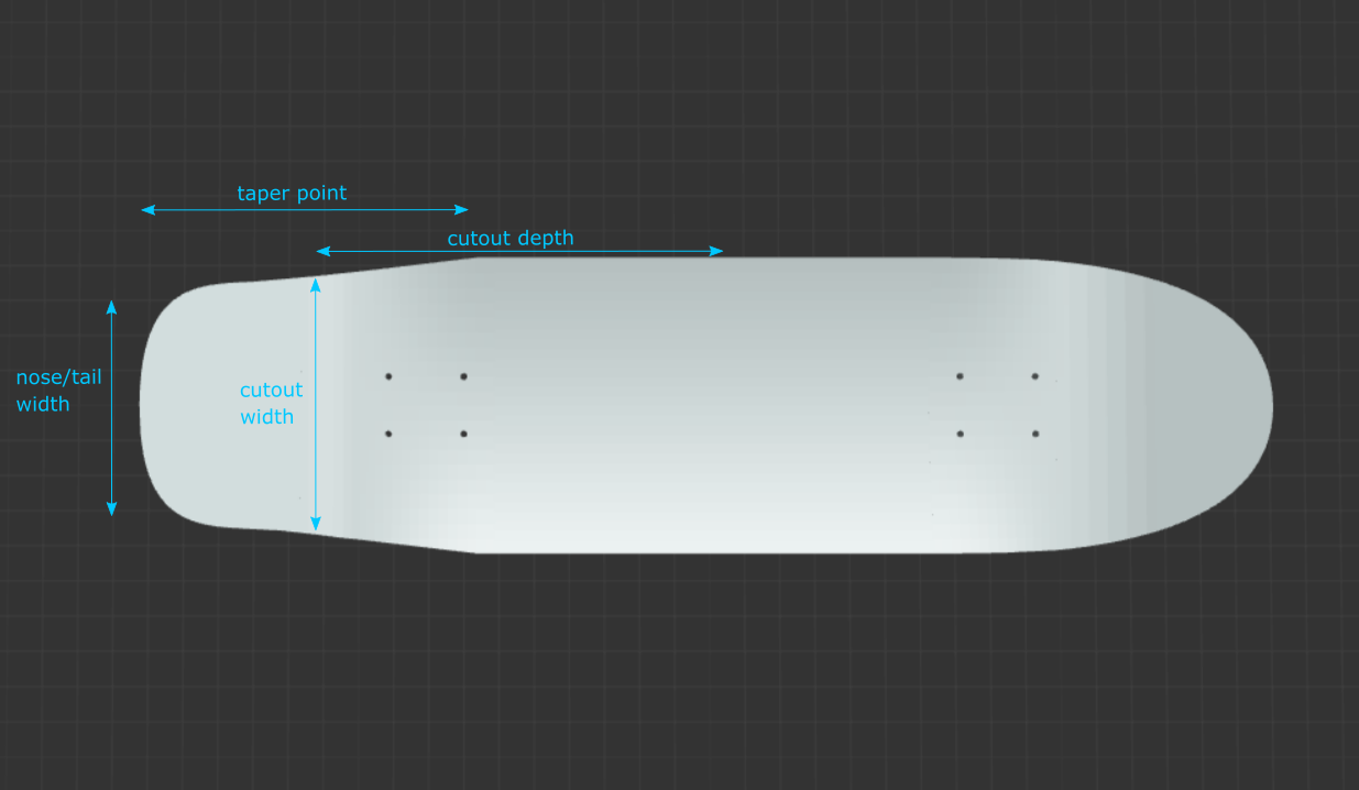
Above: approximations of the cutout parameters' influence on board shape. The shape of the board is actually created from Bézier curves. One anchor point is at the tip of the nose/tail, and the other anchor point is at the nose/tail taper point. The nose/tail shape controls the distance the control points are from the anchor points of a cubic Bézier curve. The "cutouts" feature creates a fourth-order Bézier curve, and each cutout parameter controls a control point.
Instant Update: uncheck this box to prevent the model from rendering every time you change a parameter (use the “Update” button in the bottom left to render the new model).
To design fingerboards in SK8CAD, you must design your board in
It is highly recommended that you first select the "Fingerboard" design from the Example Shapes dropdown to provide a starting point, or choose one of the fingerboard shapes from the Shape Library.
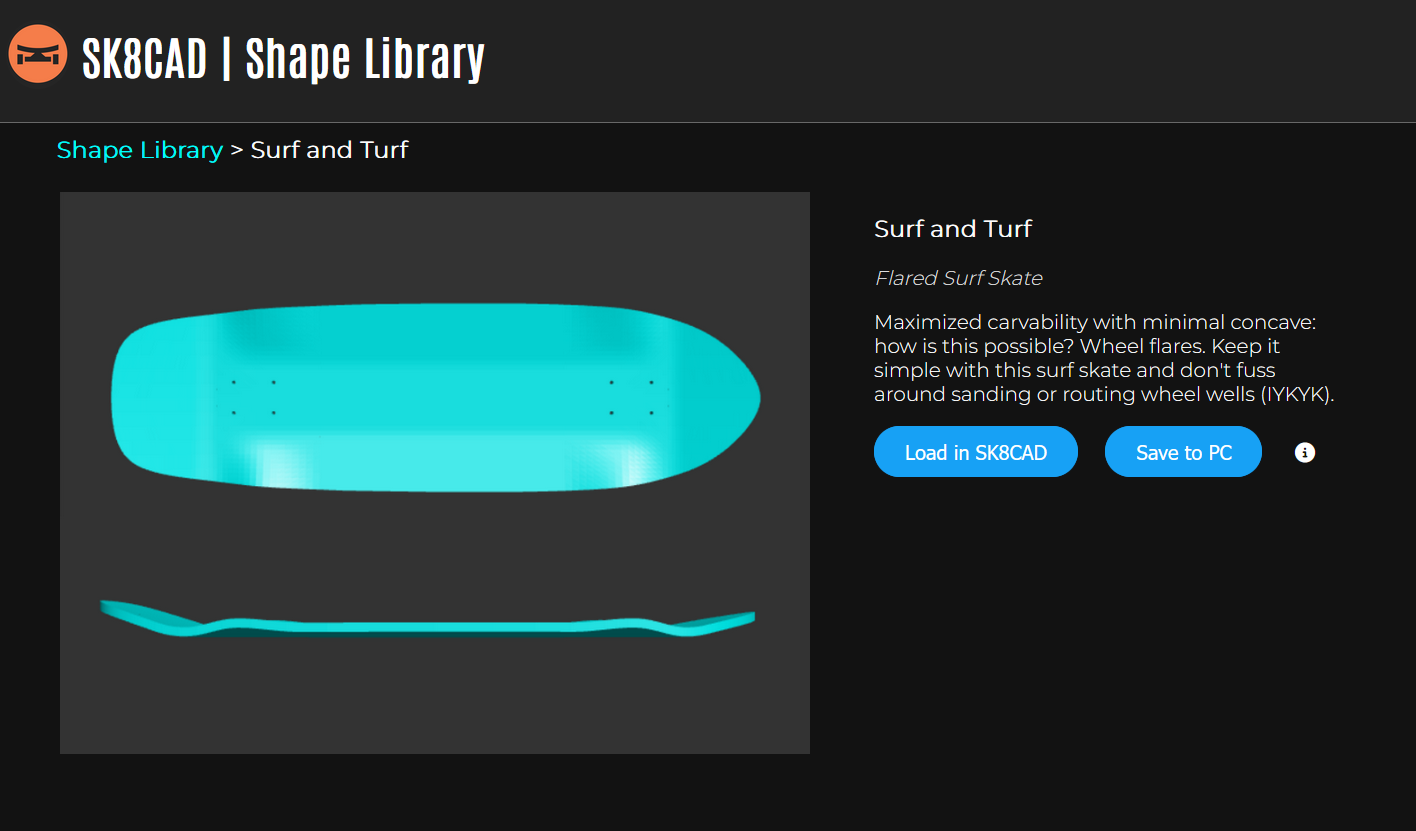
The SK8CAD Shape Library contains many pre-designed example shapes (shortboards, longboards, fingerboards, and more), and will continue to grow. This is a more extensive catalog of shapes than the Example Shapes dropdown menu provides. Subscribe to the "Lite" plan to get access to the Shape Library.
SK8CAD is built using the OpenJSCAD platform. The "</>" button in the "About" window (top nav -> Help -> About) allows you to edit the OpenJSCAD script. To rerun the code with your edits, press Shift + Enter. The User Guide for OpenJSCAD can be found here: User Guide PDF
Support our work to democratize skateboard manufacturing:
|
Recurring support and supporter-only benefits. |
Leave a tip via PayPal. |
Thank you for your support, and happy skating and creating!
For questions, and to discuss SK8CAD, please join the SK8CAD Users Discord Server.
For direct support, please upgrade your SK8CAD subscription:
Want to stay in the loop? Join our email list to receive very occasional emails.
To get in touch, please visit https://opensourceboards.com.